
Electric and magnetic fields are important factors to be considered when designing transmission lines. They occur in nature and have become much more prevalent in our everyday lives through man-made sources such as electric power. When planning transmission lines it is important that designers have a reasonable understanding of the nature of both so it can be considered during design; understand the effects of electric and magnetic fields from transmission line operation including corona; and mitigate these effects by modifying the design, where possible.
Properties of Electric and Magnetic Fields
Electric fields are produced by voltage, and magnetic fields are produced by current. Electric fields and magnetic fields manifest themselves in different ways and have different characteristics. For example, an electric field is easily shielded by an object, such as a tree or a house, while a magnetic field is not. The presence of an electric field may cause a shock when touching a metal object, such as a fence or car, near a transmission line. The shock is caused by the body of the observer spanning a voltage gradient. A magnetic field has the ability to induce a current in a conductive object – for transmission lines this would require a long conductive object to be in close proximity to the line in order to have a noticeable effect. An example would be a parallel railroad or fence.
Electric and magnetic fields are coupled – therefore related to each other – when the distance to the source is much larger than the wavelength. However, when the wavelength is much larger, they are un-coupled and the effects of each should be considered separately. For low frequency fields, as is the case with power systems, the wavelength is about 3,100 miles and much larger than the typical distance of concern from the source, and therefore, the two are un-coupled. X-rays are an example of a coupled source. When electric and magnetic fields are coupled, they are referred to as electromagnetic fields; when they are not coupled, they are referred to as electric and magnetic fields. Both terms are abbreviated as EMF.
The actual EMF at any point in space is the cumulative EMF from all sources, and the magnitude and direction of all sources are summed to give the total EMF. Depending on the direction of each individual EMF source, they may partially add or partially cancel. The nature of the EMF, whether it be alternating (AC) or steady-state (DC), will also determine its properties.
Environmental Effects of EMF
Historically, research on the effects of EMF on an individual’s health has been inconclusive. The most recent research suggests that there is no link between EMF and adverse health effects. But despite these research findings, negative public opinion remains. The health concerns originate from early scientific studies that show that exposure to magnetic fields generated from low-frequency power systems may be linked to an increased rate of cancer in humans. With very high frequency magnetic fields (such as those from X-rays), because of the exceptionally high rate at which the forces alternate, the wave generated can cause energy to be emitted to an object, which is known as radiation. If the object is human tissue or other organic matter, this can damage chemical bonds and may eventually cause cancer or other health disorders. However, this is not the case with the low frequency fields of power systems EMF; because of their much slower alternating frequency, they do not have the ability to cause radiation.
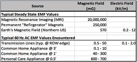
Table 1: Typical Commonly Occurring EMF Levels
Nonetheless, the health concerns remain with the general public. As previously noted, there are various sources of EMF, some natural. Table 11 summarizes the EMF levels of multiple sources present in our everyday lives. It is important to note that some are DC while others are AC. One of the main contributors to daily EMF exposure is common household appliances. Table 22 is a summary of typical appliances and their EMF levels. To alleviate public concern, multiple states limit the level of EMF strengths at the edge of the transmission line right-of-way (ROW). There are also several regulatory agencies that publish recommendations for EMF exposure to the general public, the International Commission on Non-Ionizing Radiation Protection (ICNIRP) being the most prominent.
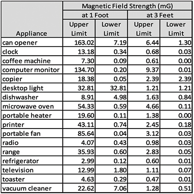
Table 2: Typical Magnetic Fields of Home Appliances
A sample of these values is shown in Table 3.3 . Further evidence of the negligible impact of power systems’ EMF is the fact that the levels of permissible EMF exposure from power lines published by ICNIRP were more than doubled when revised in 2010 as compared to the levels established in 1998.
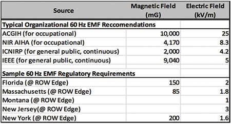
Table 3: Typical Published EMF Limitations
Even though it is believed that there is a minimal, if any, link to adverse health effects from low frequency AC EMF, there are other potential adverse implications of EMF in the operation of a transmission line.
Potential effects of electric fields from the operation of transmission lines include:
- Spark discharge as a person touches metal object near a transmission line
- Fuel ignition, pole fires, or dead tree burning by spark discharge
- Induced voltages and sparks during construction activities if other live lines are present
- Interference with heart pace-makers or other electrical devices
- Damage to fiber optic cable by dry-band arcing
- Corona discharge and its effects – audible noise, line losses, etc.
Potential effects of magnetic fields from the operation of transmission lines include:
- Induction of current in parallel wires or other long metal objects
- Interference with computer monitors or other magnetic devices, such as compasses
EMF Reduction
There are many factors that contribute to the intensity of EMF. The two most critical factors in calculating EMF are the distance to the source and its electrical properties of voltage and current. Typically, the voltage and current are driven by load demand and cannot be reduced whereas the distance to the source is driven by cost (because a higher line requires taller and more expensive structures) and is not easily increased. If the EMF of the individual conductors can’t be reduced, it must be accounted for and mitigated properly by the transmission line designer through the employment of other methods.
The EMF experienced by an observer is cumulative to the EMF produced by each source in the area. The conductors can be phased within a circuit so that the EMF emitted by each can partially cancel the others; or if more lines are present on the ROW, their conductors can be phased as well to allow for additional EMF cancelling. Often times, if a new line is constructed on an existing ROW, it can be phased to allow for a lower EMF post construction. Phasing will sometimes create a higher peak EMF near the center of the ROW with a lower EMF at the ROW edge; however, the edge is typically the location subject to regulatory requirements.
Another option is to alter the configuration of the line. The location of the conductors and shieldwires within the circuit can have a significant effect on EMF. For example, a vertical line has conductors higher than a horizontal line reducing their effective EMF at ground level; and a delta configuration will have a similar effect. A reduction in phase spacing generally correlates directly to a reduction in magnetic field, so the location and quantity of shieldwires can also affect EMF and should be examined. Hardware modifications, like the addition of V-strings that may move the conductors up and closer to the center of the ROW, can have similar effects.
Non-traditional designs for line configurations can also be employed to further reduce EMF. As shown in Figure 1, a transmission line can be designed as a dipole by using bundled conductors and energizing traditional A and B phases, but altering the C phase to have one sub-conductor opposed to the A phase and one opposed to the B phase instead of 120 degrees out of phase from each. Additionally, all three bundles can be split and oriented alternately (such as a circular or hexagonal arrangement) to allow for EMF cancelling.
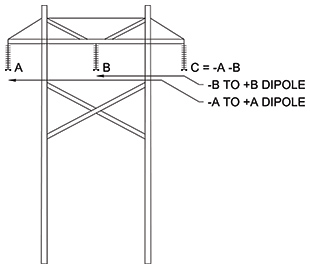
Figure 1: Transmission Line as a Dipole
In certain circumstances, it may be appropriate to install a passive shield line to reduce EMF on an existing circuit. The passive shield line is a ‘dummy’ line that emits EMF, which directly opposes the EMF of the transmission lines. The ‘dummy’ line would be a short line that forms a closed loop under each side of the transmission line of concern. Using the current induced by the magnetic field of the transmission line, it emits its own magnetic field and can be designed and phased to effectively cancel out the existing EMF. However, modifications can be costly, visually unappealing, and would increase line losses.
Properties of Corona
Corona is a phenomenon that occurs as a result of high electric fields and has adverse electrical and environmental effects. Corona is a discharge of electricity from an energized surface. The discharge occurs when a highly concentrated electric field causes the air surrounding the surface to become ionized. Electrons are regularly discharged from an energized surface, but when the electric field is concentrated enough and exceeds a certain critical value, the single discharged electron collides with the air molecules and causes the release of their electrons. If a chain reaction of discharging of electrons from the surrounding air molecules – known as an electron avalanche – results, corona has occurred.
The surface condition of the energized material plays an important role in determining the critical value of the electric field at which corona discharge can occur. Any defect on the surface of a conductor that disrupts smoothness greatly increases the intensity of the electric field, increasing the likelihood of corona. Surface irregularity examples include: broken strands on a conductor, sharp edges on hardware, water droplets on a conductor, or abrupt changes in charge of hardware (which could occur at an insulator).
Conductor diameter is a variable that can affect the critical value for the formation of corona and is typically governed by the load required to be carried by the line. However, the use of bundled conductors allows the line to carry the same load with smaller diameter conductors, effectively raising the corona threshold and reducing the likelihood of corona. Air density is another variable that is proportional to the critical value – a decrease will cause a reduction in the critical value. This could occur in a higher elevation or, possibly, with the use of high temperature conductors that heat the air in the vicinity of the conductor. Weather conditions will also contribute to corona. As noted above, the presence of rain droplets and lines near the ocean that may have salt deposits or those near contaminated generating facilities will all increase the surface irregularity.
Environmental Effects of Corona
The electron avalanches of corona create streamers or discharges of electricity. This causes rapid heating of the air before it has time to expand and results in something similar to a tiny explosion. Many of those in sequence will create a noise that can be heard as a slight crackle or hum. The audible noise created by corona can not only be a nuisance, but a governing design constraint. According to the Electric Power Research Institute, the threshold noise level for abutter complaints to occur is approximately 53 decibels (dB) at ROW edge.
These discharges emit light seen in the dark and can also create electromagnetic interference with radio and analog TV broadcast signals; which are most significant in the AM radio bands. The process of ionizing the air also results in the creation of ozone – a gas that is commonly understood to be harmful to Earth’s atmosphere. These effects, along with the process of ionizing the air, use energy and that energy comes from the transmission lines and results in power loss. Typically, though, audible noise limitations will govern the design before these other factors.
Corona also causes hardware degradation over extended periods of time. The corona streamers cause the hardware to heat up and may result in cracking or other defects. Because of their configuration – with an abrupt change from the energized fitting to the fiberglass insulating rod – polymer insulators create a higher electric field than is present on other transmission line hardware. This results in a lower threshold for corona and the streamers can easily damage the weather seal between the sheath and the fitting or the sheath itself. This is also exaggerated by the presence of water droplets following a rain storm. Because the fiberglass core needs to be completely isolated from weather, polymer insulators are especially susceptible to catastrophic failure due to corona.
Corona Reduction
The main area of concern for reduction of corona is hardware assemblies for extra-high voltage lines. This includes 345-kilovolt (kV) lines and above, but the designer may wish to employ corona mitigating techniques described below to lower voltage lines on a case-by-case basis, if warranted. Any sharp edge can cause the onset of corona – an exposed cotter key, the 90degree angle of a bolt head, the sudden terminus of the tip of a compression deadend or even armor rods can be enough of a disruption of the smooth surface to cause the onset of corona.
It’s important to procure hardware that is ‘corona-free’ or rated for ‘[extra]-high voltage.’ When this is specified, manufacturers will supply parts with tapered edges or rounded caps to cover protruding objects. Figure 2 shows examples of corona-free versus traditional hardware.
Figure 2
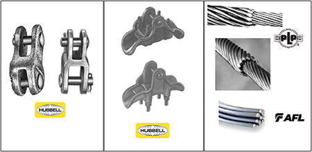
| Corona-Free (Left) vs. Traditional (Right) Clevis Clevis Clevis Hardware |
Corona-Free (Top) vs. Traditional (Bottom) Suspension Clamp |
Corona-Free (Top Two) vs. Traditional (Bottom) Armor Rods |
The energized end of an insulator is generally subject to higher electric fields. Corona is mitigated at this location by the introduction of a corona ring to the hardware assembly. A corona ring is a conducting ring that mitigates corona by expanding the electric field beyond the first insulator and dispersing the electric field over a larger area. (One may also be applied to the cold end as well, depending on the line’s characteristics.). The size and shape of corona rings may be adjusted to account for a range of hardware and insulator configurations; the designer should always consult the corona ring manufacturer to determine the appropriate application. Because of the high potential for damage and the severity of the failure mechanism from corona in polymer insulators, the designer may wish to employ the use of corona rings at voltage levels as low as 115 kV.
Finally, corona can be mitigated through post construction inspections performed on locations where corona is of particular concern. This might include highly contaminated areas; extra-high voltage lines, such as 500 kV and above; lines with polymer insulators; or lines where audible noise has been reported. Retrofitted hardware can be installed if high levels are detected. Routine maintenance should be conducted in a timely manner and include the washing of insulators in areas with high potential for contamination as well as visual inspection of the lines to mitigate any defects in the smooth surfaces, such as a damaged conductor, backing out of cotter pins, or loose hardware.
By initially limiting EMF and corona and then employing mitigating techniques where necessary, a design can be produced that is satisfactory for all stakeholders.
About the Author
 James Hannigan is a senior transmission line engineer for SAIC. He has a master’s degree in civil engineering, with a structural emphasis from Worcester Polytechnic Institute and has more than eight years of experience in transmission line design focused in licensing and permitting, rehabilitation of existing lines, and design of wood pole structures.
1 Electric and Magnetic Field (EMF) Analysis of Expansion of Lines Originating at Millbury Substation, 2009; Gradient LLC; [Massachusetts] D.P.U., [Docket] 09-136/137, Exhibit PAV-3; http://www.env.state.ma.us/dpu/docs/siting/09-136/12409nepptp6.pdf
2 Electric and Magnetic Fields Measurement and Possible Effect on Human Health – What We Know and What We Don’t Know in 2000 [Fact Sheet]; California Electric and Magnetic Fields Program, State of California; Gray Davis, Governor; http://www.ehib.org/emf/longfactsheet.PDF
3 Electric and Magnetic Field (EMF) Analysis of Expansion of Lines Originating at Millbury Substation, 2009; Gradient LLC; [Massachusetts] D.P.U., [Docket] 09-136/137, Exhibit PAV-3; http://www.env.state.ma.us/dpu/docs/siting/09-136/12409nepptp6.pdf


